| |
| |
|
| |
| |
| |
||
| |
||
| |
||
|
|
|
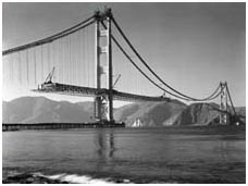
the Golden Gate Bridge

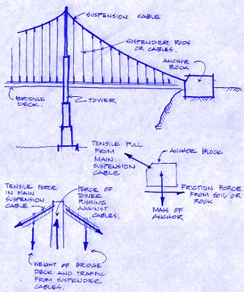
Strauss was a unique individual, and insisted that workers be protected to a much greater degree than had been the norm. He commissioned Edward W. Bullard, a local manufacturer of safety equipment, to design protective headgear, and insisted that it be worn on the job. This was a prototype of the hard hat, and, together with glare-free goggles, marked the first time that this sort of equipment was worn on the job. In addition, skin and facial creams protected workers against the wind and sun, while special diets helped fight dizziness. The most visible precautions were safety nets, suspended under the bridge deck along its length. During construction, the net saved the lives of nineteen men, although on February 17, 1937, ten men lost their lives when a section of scaffold carrying twelve men fell through the safety net. In a suspension bridge, the weight of the bridge deck and vehicles is transferred up through the suspender rods or cables to the main suspension cable, which, in turn, transfers forces to the bridge towers and the anchor blocks. The forces from the suspender rods produce tensile forces in the main The anchor block, on the other hand, resists the tensile pull from the main cable primarily through its mass. As sketched, the tensile pull or force from the main cable is balanced, or equilibrated (put into a state of equilibrium) by the gravitational pull on the mass of the anchor and the resulting frictional force between the anchorage and the foundation on which it sits. In most suspension bridges, the anchorage is a reinforced concrete block cast against and firmly connected to underlying rock. Inside the anchor block, the stranded suspension cable is unwound and splayed out to provide a more substantial connection between the concrete and the cable. 
The design of a suspension bridge is a complex task requiring significant mathematical skills and engineering ability. As an example, consider the fact that all materials will deform (e.g. lengthen, shorten, or bend) to some degree when subjected to a load or force. In a structure such as a suspension bridge, the designer needs to know the range of movement the deck will undergo at various points due to a variety of applied vehicle loads—from no traffic at all through to heavy truck traffic in stop-and-go conditions during rush hour. The movement of the deck is affected by its own weight, the range of temperatures it undergoes, the amount and behavior of vehicle loads on the deck, the velocity of the wind, the downward sag (deflection) of the deck between suspender cables, the amount of stretch or elongation of the suspender cables, the shortening of the towers, the elongation of the main suspender cables due to force and some ‘untwisting’ of the wound strand, and posssibly some movement of the anchor blocks. All in all, a daunting problem, and one reason why the study of Civil Engineering Technology requires not only ability, but a commitment to hard work and excellence…  Click for a larger (48k) graphic Click for a larger (48k) graphic |

 suspension cable—that is, forces which attempt to stretch or lengthen the cable. The main suspension cable, which sags in an approximately parabolic shape, is not a solid steel cable, but is made up of a number of small-diameter steel cables which are wound together to produce a large stranded steel cable. Where the main suspension cable meets the towers, it runs through a smooth saddle, which enables it to transfer forces into the tower as shown in the sketch. In simple terms, the two tension forces from the main cable pull horizontally against each other, while at the same time pushing down on the tower, which, in turn, must push back up against these downward forces. We can therefore say that the tensile forces from the cable produce a compressive force in the tower—that is, a force which tends to shorten or compress the tower. The tower must then be designed to support these compressive forces without crushing or buckling (Buckling is the sudden sideways movement of a long, slender member subject to a compressive force. Take a meterstick or yardstick, stand it on end, and push down on it along its length—it doesn't take much force to create that sudden sideways jump).